

Understanding Audio Signaling using the Mackie 1402-VLZ4 Analog Mixer
Introduction
In order to understand every function on the Mackie 1402-VLZ4 Analog Mixer, we will discuss the controls, inputs, outputs, and indicator lights. The numbers by each description are also found on the mixer screenshot above.
PAN vs BAL Controls - Functionality

I actually own the above mixer and I love it. However, I want to clarify its proper use. At first glance, this audio mixer is marketed as a 14-channel mixer by counting the mono mic channels 1 through 6 plus the remaining 8 individual Left and Right stereo channels on 7 through 14 as separate inputs (6 + 8 = 14). Theoretically, the user “could” use the Left and Right input jacks on 7 through 14 as individual inputs but they would not have complete control over the individual L and R signals. It should be noted that the mic channels have a “Pan” control, whereas the stereo channels have a “Balance” control. That is to say that the “Pan” controls on 1 through 6 will move each individual audible signal throughout the entire L+R stereo listening spectrum. However, the stereo “Balance” controls on 7 through 14 can only attenuate one side (L) while the other side (R) becomes more prominent and vice versa. Therefore, the mixer actually only has 10 usable channels (6 mono + 4 stereo = 10). That is, Channels 7/8 (Left & Right) should actually be used as only ONE single stereo channel (the same for Stereo Channels 9/10, 11/12, and 13/14). If each of the stereo channels are used as two separate inputs, then both of those L+R inputs will also share the exact same Equalizer (EQ) and Effects Loop settings (which would not be desirable in most cases). If you need to share the L and R stereo inputs on each channel, keep the BAL control in the center. However, if you routinely need the extra individual channels, it is better to spend the extra money on a mixer with enough separate mic channels to accommodate that need. Don’t get me wrong, I love using stereo mixer channels but I only use each stereo input pair (L and R) for ONE stereo instrument. They can also be used as mono channels using the L input. They are compatible with most any instrument or input device, balanced or unbalanced.
2. Volume Faders
The sliding faders on each channel adjust each channel’s volume level from “- Infinity to +10db.” The two Master sliding faders on the right adjust the Master volume of the Left and Right channels separately from “- Infinity to +10db.” This is handy when a room has obstructions or a different shape and one channel needs extra volume to make the overall sound more uniform.
3. Equalizer Controls
The LOW, MID, and HI controls are the Equalizer (EQ) settings used to shape the amplitudes in the frequency domain of the stereo listening spectrum on each individual channel. In this case, the LOW band control will adjust the amplitudes or volume levels of the audible frequencies in the range of “80hz - 15db” to “80hz + 15db.” The MID control will adjust the amplitudes or volume levels of the audible frequencies in the range of “2.5khz - 15db” to “2.5khz + 15db.” The HI control will adjust the amplitudes or volume levels of the audible frequencies in the range of “12khz - 15db” to “12khz + 15db.” The overall effect of these control settings will either improve or degrade the quality of the live stereo output to the listener. Therefore, is it important to understand how to use each of these adjustments to maximize the quality of the listening experience. Generally, I start out with each control in the center at “U” (Unity) and move out from there with the understanding that every voice and instrument is different and each sound best at their own unique EQ settings. Different microphones also have varying effects on the input source (voice or speaker).
4. Aux 1 and Aux 2 Effects Loop Controls
These controls will adjust the volume level from “- infinity to +15db” of the effect imposed on the raw audio signal. Lower settings (counter-clockwise) will produce a “dryer” effect, higher settings (clockwise) will produce a “wetter” effect. In this case, the Effects Loop audio signal is sent to an external effects processor (usually mounted in a rack) in mono and the return audio signal from the effects processor is in stereo. This mixer is equipped with two Effects Loops called AUX 1 and AUX 2 and operate independently for two completely separate effects imposed on the same audio signal from each individual channel. Effects processors come in a large variety of effects such as digital reverb, delay, chorus, flanging, etc. (or a combination of several effects in one unit).
The AUX 1 and AUX 2 loop “send” can also be used as a mono “monitor send” to a power amp or powered monitor speaker and adjust the monitor volume from each channel.
5. Gain Controls
Each Mic channel on 1 through 6 has its own gain control and is very typical of all Mic channels. Some higher-priced mixers even have these controls on the stereo channels but this one does not. These adjustments will control the gain of the preamp for each input signal and adds to the overall gain of each Mic channel. Essentially, it makes the input signal “hotter.” This makes it possible for mics with a weaker signal output to be heard through the other signals going through the mixer by making that channel input more or less “sensitive.” The degree to which this preamp gain is applied is what maximizes the “headroom” of each Mic channel.
6. Solo Buttons
Selecting any combination of the SOLO buttons will feed the sum audio of those channels to the Control Room, Headphones, and Meter Display. Whenever SOLO is engaged, all other source selections (Main Mix, Alt 3-4, and Tape) are defeated to allow the SOLO audio only to feed the Control Room output.
7. Mute / Alt 3-4 Buttons
The MUTE / ALT 3-4 button is bi-functional. It “mutes” the input audio signal entering that channel by temporarily disconnecting it from the preamp. This is particularly helpful when the system is powered up but not being used. Muting potentially noisy channels will prevent any disruptions in your event. Pressing the “Mute” button on any combination of channels also causes the sum of those channels to be sent to the ALT OUT 3/L-4/R output jacks. This is a handy way for band leaders to communicate real-time voice instructions to other band members or the sound engineer through “in-ear-monitors.”
8. Low Cut Buttons
The LOW CUT (or high-pass) buttons will filter out the low frequency audio below 75HZ which can “muddy up” or even damage the mixer channel input. It will also filter out “60-cycle hum.” If a higher frequency instrument such as an acoustic guitar is connected to the MIC inputs, I like to leave this button ON so the lower frequencies in that spectrum sound more crisp. This button has its uses for channel protection but should never be the sole replacement for a Direct Injection (DI) box. Using a DI box will protect your mixer’s MIC inputs from excessive low-frequency audio levels, provide the proper impedance matching needed to prevent noise, and maximize sound quality. Therefore, use a DI box whenever possible with instruments and use the LOW CUT buttons as needed for increased sound quality. NEVER connect a bass guitar or any other low-frequency instrument to ANY mixer input without going through a DI box first.
9. Mic Line In 1 through 6 - 1/4”
The 1/4” LINE IN inputs on MIC channels 1 through 6 are TRS (Tip-Ring-Sleeve) jacks which feed each audio input signal into the preamp. These audio input signals are MIC-level (1mV to 10mV) and can be either balanced or unbalanced. When used as a balanced input, the tip is positive (+, Hot), the ring is negative (-, Cold), and the sleeve is Shield or Ground. When used as unbalanced, the tip is positive (+, Hot) and the sleeve is Shield or Ground. These MIC-level signals pass through the awesome Onyx Preamps to become line-level signals, which is 0dBV or 1.0V (1,000 times > MIC-level).
10. Mic Line In 1 through 6 - XLR
The XLR MIC LINE IN inputs are 3-conductor female jacks and accept balanced MIC or line-level inputs from almost any type of audio signal source. The XLR pins are wired as follows:
Pin 1 = Shield or Ground, Pin 2 = Positive (+ or Hot), Pin 3 = Negative (- or Cold)
When connecting a guitar to these MIC LINE channels, go through a DI (Direct Injection) box to convert the unbalanced line-level signal from your guitar to a balanced MIC-level output and provide signal/impedance matching. Furthermore, they allow you to send your guitar signal over long cables or audio snakes with minimum interference or high-frequency signal loss.
NOTE: Never connect unbalanced microphones or instrument outputs to the MIC LINE IN channels with the Phantom Power turned ON unless the instrument manufacturer says it is safe to do so.
11. Channel Inserts (Pre-Fader/Pre-EQ, Tip Send / Ring Return)
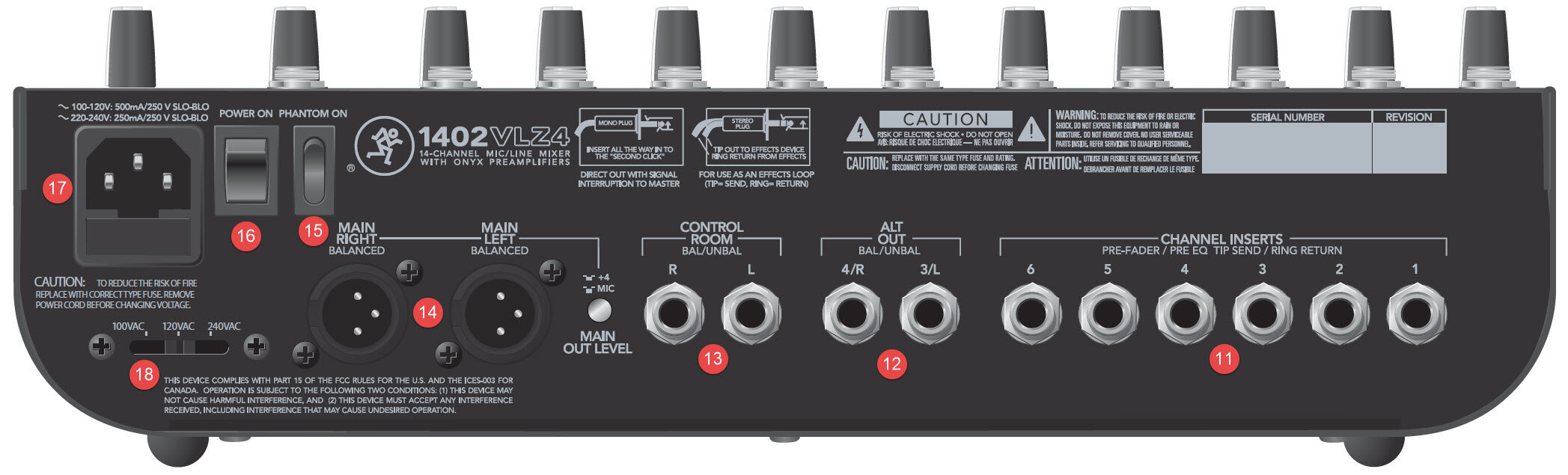
These rear panel jacks are where you connect serial effects such as compressors, equalizers, de-essers, or filters. Since most people don’t have more than a few of these gadgets, Mackie provided inserts for just the first 6 channels. If you want to use these kind of processors on channels 7 through 14, simply pass through the processor before connecting to the mixer.
The channel insert points are after the gain and and low cut controls but before the channel’s EQ and fader. The send (tip) is low-impedance (120 ohms), capable of driving any line-level device. The return ring is high-impedance ( > 2.5 K ohms) and can be driven by almost any device.
Besides being used for inserting external devices, these jacks can also be used as channel direct outputs; post-gain, post-low-cut, and pre-EQ.
12. Alt Out 3/L 4/R Bal/Unbal
These 1/4” jacks will output the sum of any channels having the “Mute/Alt 3-4” button pushed in. These are balanced outputs and can deliver up to 22dBu into a balanced or unbalanced load. These outputs are useful for isolating and sending selected channels to control room monitors or sub-mix headphones for whatever reason.
13. Control Room Bal/Unbal R & L
These outputs are for listening to something other than the main mix. You can select a source from the matrix of switches on the top main panel directly above the CR/Sub Mix fader. These outputs can feed a set of powered speakers or a sub-mixer.
14. Main Right Balanced / Main Left Balanced
These stereo output jacks are the Main Mixer Outputs with two selectable levels: Mic level and +4 dBu line level. The +4 dBu line level setting yields the stronger signal output. This is to best match the input level of the post-mix equipment used in the application.
NOTE: There are two (2) different line levels in the Audio Industry which are measured using two different unit scales:
+4 dBu (dB “un-weighted)
-10 dBV (dB Volts)
In this case, the +4 dBu is a stronger output signal than mic level. The -10 dBV is NOT available at this output. The -10 dBV is normally found only at the inputs of commercial audio equipment to amplify the input signal and enable consumer audio gear to interface with higher-end commercial gear.
15. Phantom Power ON/OFF
Most modern professional condenser mics receive a low-current 48VDC phantom power from the mixer on the same wires as the audio signal. Semi-pro condenser mics often have batteries to accomplish the same thing. “Phantom” gets its name from being able to be “unseen” by dynamic mics (which require no external power source) and are also unaffected by it. The mixer’s phantom power is globally controlled on Channels 1 through 6 by the Phantom Power switch on the rear panel. Never plug single-ended (unbalanced) mics or instruments into the mic input jacks with the phantom power ON. Do not plug instrument outputs into the mic input jacks with the phantom power ON, unless you know for sure it is safe to do so.
16. Power ON/OFF Switch
This rocker switch cycles the main power to the mixer. The power LED on the top surface will glow when the power is ON while plugged into an AC power source. When this switch is in the OFF position while plugged into an AC power source, it is in “standby mode.” The mixer will not function but the circuits are still live. To remove AC power, either turn off the AC mains supply or remove the end of the AC power cord from the mixer or the AC power source.
As a general rule, you should turn the mixer ON first before the power amp or the powered speakers, and turn it OFF last to prevent any power-ON/OFF thumps in your speakers.
17. Power Connection
If the power cord is lost, the power jack accepts a standard IEC 3-prong power cord like those found on most professional equipment.
WARNING: Before connecting the power cord to the mixer jack, make sure the slider selector switch is set to the same voltage as the local AC supply.
WARNING: Never disconnect the plug’s ground pin.
NOTE: Directly below the power connector jack, there is a fuse drawer with a 500mA slow-blow fuse for a 120VAC incoming voltage source setting. Use a 250mA fuse for a 220/240VAC incoming voltage source setting.
18. Voltage Source Selector Switch
Before connecting the power cord to the mixer, make sure the voltage selector switch is set to the same voltage as the local voltage supply. Only slide the voltage selector switch with the power cord unplugged. Use a flat-head screwdriver to slide the switch if needed. The switch allows you to use the mixer in different countries on different voltages.
We hope you have enjoyed reading this post. Please feel welcome to visit Electrician’s Journal often to enjoy other articles and further increase your skill set.


