

CAN Bus - J1939
Introduction
J1939 is a communications & diagnostics protocol developed by the SAE (Society of Automotive Engineers) for use in complex networks on industrial vehicles. It is used for all sorts of mobile industrial vehicles including trucks, buses, emergency vehicles, dozers, cranes, etc. It is also used in mining, forestry, agriculture, oil & gas, military, ships, generators, and any diesel engine. More specifically, J1939 is a standardized communications “language” that runs over CAN Bus. CAN Bus is the physical “medium” for the J1939 “language.” For example, CAN Bus is like a telephone and J1939 is like the language spoken into the telephone. J1939 is also referred to as a “Higher Layer Protocol (HLP) using CAN as the physical layer basis. This means that J1939 offers a standardized method of communication between ECU’s (Electronic Control Units) in one language for all manufacturers and fully supports complex diagnostics.
J1939 History
The original top level J1939 document was published in 2000 although some of the underlying documents i.e. J1939-11, J1939-21, J1939-31) were previously released in 1994. The SAE J1939 standard has replaced former standards J1708 and J1587. Due to a massive growth in IOT (Internet Of Things), transportation will be a key area of application. Since J1939 will be at the heart of scalable fleet solutions using wi-fi data loggers, the standard will only grow in importance over time.
J1939 Characteristics
J1939 speeds are typically 250kbps or 500kbps and is built on CAN 2.0B which is an extended 29-bit message identifier. These speeds are intentionally limited to 500kbps to ensure reliable communications in all practical circumstances. Messages are identified by PGN’s (Parameter Group Numbers) which use up 18 of the 25 bit identifiers. A PGN will contain a number of SPN’s (Suspect Parameter Numbers) in the 8 data bytes used for defining parameters. In short, PGN’s are the message categories and SPN’s identify the real data we’re looking for, such as engine RPM’s. The datalink consists of three wires: yellow is CAN+, green is CAN -, and Shield is connected to ground.
J1939 Message Format
Since J1939 bit identifiers can be a bit complex to interpret, most people utilize software to convert J1939 DBC files from logged or streamed data into human-readable format to obtain the actual messages they are looking for.
As shown in the diagram below, an SAE J1939 message typically consists of a minimum of 93 bits and tells users the exact source and nature of data, which can be used to diagnose issues as they arise.
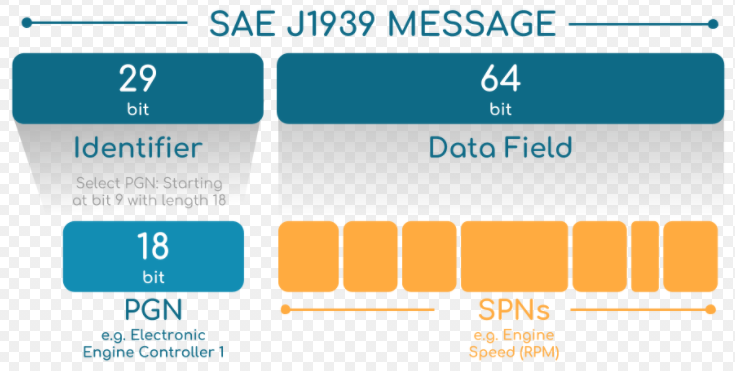
SAE J1939 messages are structured into an identifier and associated parameters, all coded into a hexadecimal format. The first 29 bits of the signal is called the “message” and identifies the source, while the remaining 64 bits are 8-byte data parameters, or “signals” associated with the message. The identifier contains a PGN, while the parameters consist of SPN’s.
Definitions of J1939 Acronyms:
PGN: A PGN is a unique ID that tells the system the function of the message and any associated data parameters. The PGN comes at the beginning of the J1939 message in the 29-bit identifier - the first three bits indicate the message priority, the next 18 bits are the PGN and the last eight bits are the source address.
SPN: SPN stands for Suspect Parameters Number and is functionally the same as a PID (Parameter IDentifier). In fact, SPN and PID numbers are nearly identical from 1 to 511, but SPN numbers go beyond 511 to over 50,000. SPN’s are grouped after the PGN in a DTC (Diagnostic Trouble Code).
Some helpful diagrams for reference below:


We hope you have enjoyed reading this post. Please feel welcome to visit Electrician’s Journal often to enjoy other articles and further increase your skill set.


