Remote Sensing Power Supplies
Introduction
If you ever have issues with the DC voltage drop at the load being lower than the output voltage setting, a power supply equipped with a “remote sense” feature can provide the necessary correction. The diagram below shows a common problem, especially with long runs of wire between the supply and the load.
Voltage Drop and Wire Size
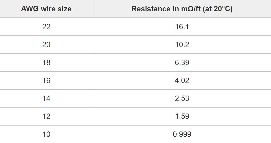
The chart below shows the resistance values for various conductor sizes in M-ohms/foot. Notice, the smaller the cross sectional area of wire, the greater the resistance. The greater the resistance, the greater the voltage drop across the leads, and the greater the loss at the load.
Wire Connections & Ground Loops
To correct this problem, connect the remote sense terminals on the power supply to the load through a second shielded twisted pair cable. Care must be taken to wire the circuit leads correctly and connect the shields to ground at one end only at the source. If both ends of the shields are grounded, this is INCORRECT and should always be avoided. This creates an undesirable condition called a “ground loop.” NOTE: A ground loop (shown below) is a voltage drop between two grounded points which causes an unwanted current to flow through the shield from the greater voltage to the lower voltage. Using shielded twisted pairs in each cable will help minimize electrical interference.
How to Correctly Connect Remote Sense Leads
The diagram below shows the resistance of each output conductor and the proper voltage drop at the load. The power supply output voltage is set directly at the output terminals before connecting the load. If the load is installed further from the source, the remote sense inputs sense the decrease in voltage and makes the proper adjustment. Thus, the wire diameter becomes irrelevant because the difference between the load voltage and the output voltage causes the source voltage to automatically adjust to compensate for voltage drop at the load. Thus, providing the original preset source voltage at the load.
Separate Shields on Output Voltage & Remote Sense Pairs
The best practice is to use separate shielded twisted pairs (as shown below) to keep the remote sense pair separate from the output voltage pair. This ensures there is no leakage sensing anywhere between the source and load which would cause erroneous voltage adjustments.
Conclusion
Most modern power supplies are equipped with the remote sensing feature. You should always use this feature whenever the load is far enough away from the source to cause a drop in voltage at the load. This feature will drastically improve the performance of power supply circuits and will likely prevent voltage-drop problems from occurring in remote equipment installations.
We hope you have enjoyed reading this post and found it helpful. Please feel welcome to visit Electrician’s Journal often to enjoy other articles and further increase your skill set.


