
Understanding Neutral Current
Introduction
Neutral current is perhaps one of the most misunderstood and overlooked topics in the electrical field. Having a good understanding of how neutral current affects the safety and reliability of an electrical system will greatly change the way you look at AC or DC circuit design. However, in this post we are focusing on concepts that apply specifically to AC circuit neutrals.
“Neutral Current” Formulas
In a balanced single-phase or 3-phase system, the calculated neutral current is always = zero. In either case, if the neutral current is a non-zero value, the system so longer “balanced.” Neutral currents must be closely considered to ensure the safety and reliability of electrical installations. The formulas below are for calculating neutral currents in single-phase and 3-phase systems and should be committed to memory.
For Single-Phase: (NOTE: Always substract the smaller current from the greater current so the result is always positive.)
N Current = L1 Current - L2 Current
For Three-Phase:
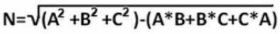
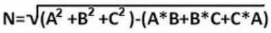
In order to easily remember the three-phase neutral current formula, I made up a “silly, short story with catchy phrases.” This makes it easy to remember not only the formula itself but also how neutral current works. Here it is:
“Someone spilled SOS on the floor in the house. In order to remove it and have Nothing left, they had to SOP it up.”
Explanation: “Someone spilled SOS (like “sauce”) on the floor in the house (under the square-root symbol). In order to remove it (minus “-” sign or difference) and have Nothing left (N = 0), they had to SOP it up.” The SOS stands for “Sum Of Squares” for each phase current. The SOP stands for “Sum Of Products” for each phase current.
Neutral Current Calculations:
Example 1: A single-phase 120/240VAC transformer secondary winding is wired to two separate loads with a shared neutral. Load 1 = 20 Amps. Load 2 = 15 Amps. Calculate the neutral current.
Solution 1: The L1 and L2 connections on the transformer secondary are polar opposites (180-degrees out of phase). Therefore, the two opposing currents through L1 and L2 will subtract and return to the source through the same neutral conductor at opposite half-cycles. Thus, the difference between the L1 and L2 currents is:
L1 - L2 = N (Neutral Current)
20 Amps - 15 Amps = 5 Amps of Neutral Current
There is a very interesting concept at work here…Since the L1 and L2 currents are 180 degrees out of phase, they subtract during each half cycle. However, the neutral current is in phase with L1 during the first half-cycle and in phase with L2 during the second half-cycle. This enables the current to flow at one direction at a time through the shared neutral.
NOTE: There are potential safety hazards when using a shared neutral which are further outlined in another post entitled “Dangers of Multi-wire Branch Circuits” on this site. Care must be taken to ensure the safety and reliability of circuits using a shared neutral. Opening the neutral while under power can potentially cause a voltage divider between line voltage legs and exceed the voltage rating on an appliance or equipment load, causing damage or a fire. Furthermore, connecting two single-phase loads to “like busses” (i.e. L1 and L1 or L2 and L2) while sharing a neutral will cause the neutral currents to add instead of subtract and potentially exceed the ampacity of the neutral conductor…potentially causing a fire.
As a rule, because of safety considerations, I avoid using a shared neutral whenever possible.
Example 2: A single-phase 120/240VAC, 2-pole circuit breaker is wired to two identical 120VAC singe-phase induction motors with a shared neutral. Each motor has a full-load current of 7.5 Amps and are driving two separate identical fans. Calculate the neutral current.
Solution 2: It is important to note that the application uses a 2-pole circuit breaker, which insures the L1 bus is connected to motor #1, the L2 bus is connected to motor #2, and the two load currents are 180 degrees out of phase. Since the two loads are identical, then the currents will be (for all practical purposes) the same as well. Therefore, the neutral current is:
L1 - L2 = N (Neutral Current)
7.5 Amps - 7.5 Amps = 0 Amps of Neutral Current
Therefore, this is a “balanced” single-phase system.
NOTE: If one of these two fan motor hot wires were moved to a different circuit and connected with both hots on the same bus (i.e. L1 and L1 or L2 and L2), then the currents would not cancel but ADD and could overload the neutral conductor…especially if the fan became obstructed or the fan motor was just dirty and caused an increase in amp-draw.
Example 3: A 480VAC, 3-phase source is connected to three identical 277VAC single-phase lighting circuits with a shared neutral. Assuming the distances to the lighting fixtures are the same, what is the neutral current?
Solution 3: Since we are dealing with a three-phase panel, all three of the identical lighting fixtures would need to be ON simultaneously AND connected to three opposing power busses to achieve a balanced load and cancel all neutral currents to a net zero amps. However, that is not the likely scenario amongst multiple single-phase lighting fixtures. Furthermore, the fixture amp-draws are not given. Therefore, the neutral current cannot be calculated. If any of the single-phase loads are connected to common busses while sharing a neutral, then those neutral currents will add instead of canceling, and could potentially exceed the ampacity of the neutral conductor…potentially causing a fire.
Example 4: A 208Y/120VAC, 3-phase source is connected to a small lighting panel which supplies power to four identical 120VAC single-phase fluorescent lighting circuits. The loads on each circuit are: Circuit #1 (phase L1) = 5A. Circuit #2 (phase L1) = 4.25A. Circuit #3 (phase L2) = 7.5A. Circuit #4 (phase L3) = 10A. All wires in the four circuits have 12AWG THHW wire with a shared neutral. Calculate the neutral current.
Solution 4: Begin by calculating the total current on each of the 3 phases. L1 current = 9.25A, L2 current = 7.5A, and L3 current = 10A. By substituting each phase current into the Neutral Current formula below, the neutral current is 2.22 Amps. This small imbalance is perfectly acceptable and well within the ampacity of 12AWG wire at 75 degrees C. However, again, the same two hazards exist here. If the neutral conductor on circuits with opposing phases is lifted while under power, the 208VAC line voltage between opposing phases will divide between the two fixtures based on their internal resistance. This could cause damage to the ballasts and potentially result in a fire. Also, if one of the circuits are moved to a common bus while sharing a neutral, the neutral currents will add instead of canceling…potentially exceeding the ampacity of the neutral conductor.
For the above reasons, I personally avoid using shared neutrals whenever possible because they are only safe IF the neutral is never lifted while under power AND if all common single-phase circuits sharing a neutral remain on opposing phases. I think they’re dangerous and the risk of fire, personal injury, and property damage is not worth the savings in copper from not running separate neutrals. Many electrical contractors use shared neutrals to cut corners and save money on wiring. I do NOT endorse that practice. However, for that reason only, shared neutrals are unavoidable. We will always encounter them. Careful consideration should be taken in each application to determine if shared neutrals may present a potential hazard to people or sensitive equipment. If you must use a shared neutral, the neutral current should ALWAYS be calculated to prevent the possibility of a fire hazard. Also, the necessary precautions should always be taken (such as using pigtails at shared connections) to prevent potential hazards when live neutrals are disconnected. Above all, circuits with shared neutrals should always be clearly AND durably marked AND bundled with wire ties to indicate to all electrical personnel that circuits are sharing a neutral. This requires education among the electrical community from electricians to electrical engineers. ONLY qualified AND thoroughly trained personnel should work on circuits with shared neutrals.
I hope you’ve enjoyed this post and found it useful. I suggest reading this material several times to commit the basic electrical concepts to memory and grow your skill set. Please feel free to visit often and share this valuable resource with others. 😁